Honda CRX Forum banner

Cut Wires

2 reading
1.8K views 15 replies 2 participants last post by  connerfur  
#1 ·
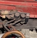
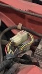
Let me start off by saying that wiring is not my best quality. Since the car isn't back yet, I've been going through the wiring diagrams in the factory repair manual for some time and this one leaves me scratching my head. The wiring diagram makes me think that this is the Dashpot control solenoid valve but the connector is behind the air intake manifold. I can't see where there is a junction going into the Dashpot valve but the wire colors look like that's the case. For the record, that is a solid blue and black/yellow. Blue 1 on the diagram connects to B2 on the ECU for an SI. Any thoughts?
 

Attachments

#4 ·
So...the last owner was correct about this not being the original engine. I was looking for wiring info as my 88 factory manual wasn't showing the Fast Idle Solenoid Valve. I found a thread online on Honda-tech that stated that it is an 89-91 add. Hmm. Not sure it even needs to be there at this point unless they changed out the wiring harness for the engine. right??
 
#6 ·
I ended up putting a "new" ecu in it when I bought it last year. It was a PM8 as was what I pulled out. Too much water damage on the old one. Fixing all the holes in the body before it goes back in. It looks like I would have to disconnect the Dash Pot to hook it up. I'm thinking for now that I'll get it running and go from there with it.
Thanks!!!
 
#9 ·
First off, I have to thank you Bobski!! Did some more digging today and it looks like they basically left some of the stuff from the 88 connected to the newer D16A6 but, as you know, not the FISV. Now that I've compared vacuum line diagrams I fully intend to take your advise and reconnect the FISV when I get the car back. Looks fairly simple to remove the Dashpot since it shouldn't be part of the vacuum system for this motor to begin with. I found the wiring diagram for the later model and they both used the same ECU location and the same blue/black-yellow so I'm planning to cut the wires at the dashpot and connect to the FISV wires. The harness in the car is the 88 harness and doesn't have the 8 pin connector at the fuel injector resistor box.
 
#10 ·
What dashpot are you talking about? I'm familiar with the one on the DPFI setup, one for EGR on some models, and a "soft-close" dashpot that catches the throttle lever if it snaps closed.
The harness in the car is the 88 harness and doesn't have the 8 pin connector at the fuel injector resistor box.
Resistor boxes I've dealt with have had 6-pin connectors with one position blocked off. '92-95 engines have an 8-pin junction-cap-connector in more or less the same place (electrically and physically). Is that what you're thinking of? I suppose C-series (V6) resistor boxes would have 8 pins.
 
#11 ·
The one on the left in the service manual is referred to as the Dashpot control solenoid valve. I’m thinking it does something similar to the FICV. The connector I mentioned was only located near the resistor. I don’t have a clear picture of the 88 but it was described in a post as having 6 wires and rectangular ( I have rectangular) vs the round 8 wire connector on the A6’s with the FICV. On the newer models the blue and blk/yellow apparently are wired through that side of the bay through the round connector. Sorry for the confusion on the connector.
 

Attachments

#13 ·
Ah, we're talking about an engine harness to main harness connector then. That would be these ones versus those ones. They use the same terminals and seals, so you could de-pin your existing connector (lift a tiny plastic lever, pull the wire and terminal out the back) and snap them into the 8-pin version if you need the two additional spaces.

I didn't realize (or maybe forgot) that early models used that TB dashpot for idle control, though I agree it makes perfect sense. Maybe they weren't getting enough idle boost by holding the TB open so they switched to the dedicated valve?
 
#14 ·
Perhaps. I feel a lot better about my ability to read a diagram now that you identified the part for me. I’ve been scratching my head all winter wondering what I was missing LOL. I think I’m going to run a wire from the cut over to the DP. In the 88 wiring that’s the only existing way to get the blue and blk/yel. To the ECU. They must have change the harness feeding the ECU when that put in the FICV.
I can’t thank you enough. It all makes sense now that I know what the heck it is and why it’s not in the 88 manual. 😂
 
#15 ·
No problem.
That throttle dashpot goes straight to manifold vacuum on later engines.

If you want to make an extension harness, repair cracked wires or whatever, you can find Sumitomo MT-type (they're rarely genuine Sumitomo-brand) connectors on AliExpress, and a smaller selection of them for 2-5x the price on Amazon. They typically come with the crimp terminals and seals, but you'll need an open-barrel crimp tool to install them - maybe $25 for a decent one. Make sure it has both the B-shaped dies for the conductor crimp and circular for the seal crimp.
To find a specific connector, go to one of those connector info pages I linked above and click the highlighted "Connectors" tab at the top. That will take you to a search page. Click the green "Included old models" check box, scroll down to "Connector series" and check the four HM and MT check boxes to save time. The heavier spade-terminal connectors (engine to main harness on the right shock tower, blower resistor, main relay, etc.) are under "250 type connector" if you're looking for one of those. Fill out any other info you know, number of positions being the big one. Find the connector in the results, search for the part number in Ali/Amazon.